Observer nTAP Optical to Copper Conversion

Copy traffic from one full-duplex optical link to one copper monitoring device
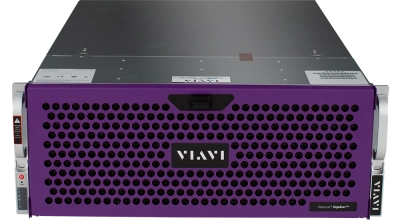
Image

  • Copies traffic from one full-duplex optical link to one copper monitoring device
  • Connects to the full-duplex link under test and an analyzer equipped with a dual-receive capture card
  • Compatible with network analyzers, security monitoring devices, forensics tools, remote monitoring appliances, and RMON probes

Install Observer Conversion nTAPs on 10 Mb, 100 Mb, or 1 Gb links for quick, anytime access to network traffic. When analyzers and similar monitoring devices communicate over different topologies than the network, Optical-to-Copper or Copper-to-Optical nTAPs bridge the gap. Conversion nTAPs make copies of network data, sending one back to the network and the other out for analysis.

For single-receive devices, Observer Aggregator Conversion nTAPs merge full-duplex links into single streams for transmission to up to two single-receive analysis devices. Industry-leading buffer sizes offer less likelihood of lost packets than SPAN ports to ensure critical traffic reaches analyzers, remote monitoring appliances, and forensics tools.

nTAPs are passive, full-duplex devices, offering complete visibility to monitoring devices regardless of traffic level. They work with the leading management tools for quick and easy deployment. nTAPs are transparent for monitoring critical links, and provide continuous network data flow even if power fails. nTAPs are scalable, modularized, space efficient, and economical.

Which nTAP do I need? Tap vs Span

Place an Optical to Copper nTAP between two devices of interest on a 1Gbps full-duplex optical link. Then attach a 1Gb copper monitoring device to the nTAP. To successfuly analyze the full-duplex output from the TAP, the monitoring device must be equipped with a dual-receive capture card.

Dimensions

Depth 7.66 in / 19.46 cm
Width (faceplate front) 5.85 in / 14.86 cm
Width (back) 4.55 in / 11.56 cm
Height (faceplate) 1.10 in / 2.79 cm

Options

Multimode (62.5 μm) Multimode (50 μm) Single-mode (9 μm)

Optical

Maximum Insertion Losses (dB)

Split Ratio Multimode 62.5 μm Multimode 50 μm Single-mode 9 μm
  (1300 nm) (850 nm) (1300 nm) (850 nm) (1310/1550 nm)
50/50 3.9/3.9 dB 4.7/4.7 dB 4.5/4.5 dB 5.5/5.5 dB 3.6/3.6 dB
60/40 3.0/5.0 3.8/5.7 3.7/5.6 4.7/6.6 2.8/4.8
70/30 2.3/6.3 3.0/7.0 2.9/7.0 3.9/8.0 2.0/6.1

Supported Media

Fiber type Multimode Single-mode
Connector LC LC
Fiber Diameter(s) 50 μm or 62.5 μm 9 μm
Wavelength Ranges (dual window) 850 nm or 1300 nm 1310 nm or 1550 nm

Environmental Requirements

Specification Operational Range
Temperature Range (operating) -40° to 185° (F) / -40° to 85° (C)
Temperature Range (storage) -52° to 185° (F) / -47° to 85° (C)

Copper

Supported Media

Interface Media
Link A/Link B (Link under test) RJ45
Copper Analyzer Interface RJ45

Environmental Requirements

Specification Operational Range  Storage Range
Temperature range 32° to 120°F / 0° to 55 °C  32° - 167°F / 0° - 75°C
Humidity 35-85% (non-condensating)

Power Requirements

Specification Measurement/Value
AC Input 90 V to 264 V, 47 Hz to 63 Hz
Operational Voltage 5 V (+10% to -5%, < 100 mV ripple)
Operational Current Typical: <= 1.8 amps  Max: <= 2.8 amps
Power Dissipation Typical: 8 W  Max: 14 W

Regulatory Compliance

Specification Certification
Emissions FCC Part 15 Class B
CE Mark EN61000-3-2, EN55024, EN55022A

Support at Every Step

We provide support, services, comprehensive training and the resources you need. It’s all part of what we do to maximize the value of your VIAVI investment.

Let Us Help

We’re here to help you get ahead.