什么是 MPO 连接器?
Learn all about MPO connector testing, its benefits, and how it can improve your network performance.
While MPO connectors have many benefits and advantages over typical single fiber connectors, there are also differences that introduce new challenges for technicians. This resource page provides an overview of the essential information technicians must understand when testing MPO connectors.
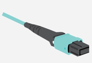
What is an MPO Connector?
Multi-Fiber Push On (MPO) is a fiber optic connector category that utilizes a linear array of fibers across a single ferrule. The most common application for MPO connectors is the termination of multi-fiber ribbon connections in high-density indoor environments.

MPO connectors have been a standard interface for dense trunk cables and have become more widely used recently in patch panel, server and switch applications. A single MPO connector can replace multiple “Sam Charlie” (SC) or LC connections, providing space savings with 12 times (or more) the fiber density in an equivalent footprint size while simplifying installation.
The MPO connection interface has been defined within the IEC-61754-7 (international) and TIA 604-5 (U.S.) standards.
To learn more about MPO connectors, watch our “Overview of MPO Connectors” video:
Click the "Read More" button below to view the transcript
Tyler Vander Ploeg: Hey everybody, I'm Tyler from VIAVI Solutions and I'm here with my colleague Matt Brown, and we wanted to talk a little about multi-fiber connectivity, and more specifically, how to do MPO connector testing. Now it's something that's been around for a very long time but Matt has been along around for the ride since the very beginning, so I wanted to bring you in Matt to talk a little bit about this and give some more depth to our viewers about what these connectors are, how they're different and what they should be keeping in mind as they're starting to experience these in the field.
Matt Brown: Sure, so almost from the beginning, not really from the absolute beginning but MPO has been around for a long time. It is a multi-fiber connector, so what is an MPO? It's a connector that has many fibers on that single connector as opposed to a Sam Charlie, which has one fiber on it or an LC, which has one fiber on it, and even you duplex them, again there's still this one fiber on each of those connectors, so an MPO is a connector that has many fibers mounted on a single ferrule. It's been around for a very long time. It's been in our networks for a very long time but it's been in a place where we don't have to deal with it or a regular technician doesn't have to touch it and manage it on a daily basis because it's been behind the panel, providing rapid connectivity of dense trunk cables and converting them into an LC form factor or elsewhere on the back plane where we don't see it.
Matt Brown: Now with a number of trends that are happening, we're really seeing that the MPO is starting to come up from behind the panel and it is on the panel and you have to deal with it so the technician is out there going what is this adaptor? What is this big rectangular thing? It's not a Sam Charlie, it's not an LC and then he gets the jumper and it's got pins on it. What thing is that? How am I supposed to put it in there? It's got this key on it. There's just a lot of things that are very different about the technology. It's a very good technology, it's a very powerful technology but it has some things that are different that we have to deal with, so that's what we should be talking about in the next series of videos.
Tyler Vander Ploeg: Yeah, perfect. Glad to have you here, Matt. We're over the next couple of videos, we'll be talking about all these things that Matt just talked about so look forward to having you with us on these. Thanks a lot.
MPO Connector Types
The exterior form factor of an MPO fiber connector includes a molded, rectangular plastic housing that is “keyed” on one side for mating and fiber position orientation. When this key is in the “up” position, fiber 1 is located on the left side. The MPO connector housing utilizes a push-pull latching mechanism with an audible click, which makes connection fast and reliable.
The density for MPO connector applications can vary between 8, 12, 24, 32 or 48 fibers, as well as 60 and 72 fiber options for specialty high-density applications. The 12 and 24 fiber options are the most commonly used today with the 12-fiber connector (MPO-12) being the first to gain widespread acceptance in data center applications. The 24-fiber connector has proven to be a mathematically convenient solution for many 40 Gig (8 fiber) and 100 Gig (24 fiber) equipment connections, which has led to a recent increase in MPO-24 utilization.
Although the connector housing size for 12 fiber and 24 fiber MPO connectors is identical, the 24-fiber option includes a second row of 12 fibers. Similarly, the 48 and 72 fiber MPO connectors include 4 and 6 rows of fibers, respectively.
The 16 and 32 fiber MPO connectors contain 16 fibers in each row rather than 12. This format has been developed specifically for 400 Gig applications. MPO technology can be used for multimode as well single-mode fiber. Multimode connectors use flat ferrules while the single-mode connectors employ eight-degree angled ferrules to minimize back-reflection. Since these connectors are similar in form but incompatible with one another, color-coding is used to easily distinguish one type from the other.
For more about MPO Connector Types, watch the “Overview of MPO Connectors” video above.
MPO vs MTP Connectors
Although the terms MPO and MTP are sometimes used interchangeably, MTP is the trade name for a specific multi-fiber connector produced by US Conec and stands for “Multi-fiber Termination Push On”. Among the proprietary design features inherent to MTP connectors are floating ferrules that improve alignment and performance under load conditions and elliptical guide pins for optimized alignment and durability.
Mechanical upgrades within the connector housing also improve reliability. This includes a modified spring design that improves ribbon clearance and a removable housing to facilitate connector gender modification and ferrule polishing in the field, as well as improved test access.
All MTP connectors are also MPO connectors, although the opposite is not true. An MTP connector is 100% inter-mateable with its generic MPO-style counterpart, but an MPO connector is not functionally equivalent to an MTP in high-performance applications, based on the tighter design tolerances and feature-set differences. The MTP connector is compliant to the same U.S. and international standards applicable to the standard MPO connector. An “Elite” version of the MTP connector is also available with reduced insertion loss compared to the standard MTP connector.
MPO Inspection & Contamination
Cleaning and inspection to control MPO connector contamination are essential best practices. Each of the multiple fibers attached to an MPO connector extends a small distance from the ferrule, meaning fiber ends physically touch when the MPO connectors are mated. This makes the cleanliness of these mating surfaces crucial. The large MPO surface area and bulkhead access can provide ample opportunities for contamination to infiltrate the connector.
The quantity of fiber end surfaces also increases the potential for contamination exponentially. For example, if we assume each fiber surface has a 90% chance of being contaminated, this becomes a 0.9012 or 28% chance that at least one fiber surface in an MPO-12 will be contaminated. Contamination on one fiber end can impact the others detrimentally by introducing Fresnel air gaps that propagate down the line or shift adjacent fibers out of alignment.
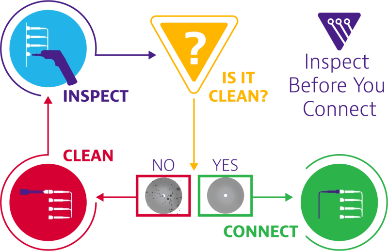
Each fiber end-face should be inspected for the presence of dust, oil, scratches or any other contaminants. If any contamination is detected, cleaning with a purpose-built MPO cleaning tool and solution is the next logical step because the wrong cleaning tool can damage the end face. After cleaning, an additional re-inspection for verification purposes should be performed prior to installation. This cleaning-inspection cycle should be repeated until no contamination is detected. Get more fiber inspection best practices.
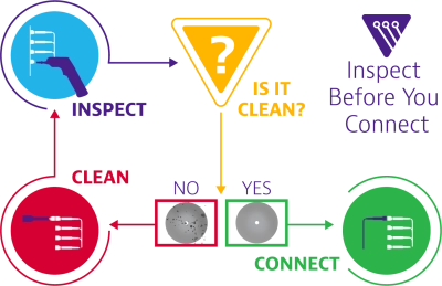
To learn more about the effects of contamination on your MPO connectors, watch our “Dealing with Contamination on MPO Connectors” video:
Click the "Read More" button below to view the transcript
Tyler Vander Ploeg: Hey everybody, I'm Tyler.
Matt Brown: I'm Matt.
Tyler Vander Ploeg: And we're with VIAVI Solutions. And in this episode, we wanted to take a closer look, specifically, about the challenges of contamination with MPO.
Matt Brown: Yeah. So there are many... a lot of things that come into play. Right? So, the first and most obvious is that with a traditional connector or an LC, you've got this ... you have this ceramic split sleeve that's in the adapter. And when you walk up to a panel and you pull that dust cap off, you can see that there's a little tiny hole. That it's a 1.25 millimeter hole that the LC connectors going to go in to, the ferrules going to go in to. If you look at an MPO on a panel, it is a giant rectangle. Right? It is a very big area.
Matt Brown: So there's just way more access and way more area for contamination to get into the interface. And right, even if you just look at the two things in your hand, the little tiny LC ferrule, which a lot of people get confused, is like, is that the fiber? No. That's a ceramic ferrule that holds the fiber. On the MPO, you've got this black rectangular ferrule that holds many fibers. So there's just a lot more surface area here for contamination to get into place, and a lot more access on the bulkhead side for contamination to get in there.
Matt Brown: The other thing that's going on is that there is one fiber on here. There's a small 1.25 millimeter fiber at the center of that 1.2 millimeter ... 125 micron fiber in the center of that ferrule. There are 12 or 16 or 24 fibers on that ferrule. So probabilities are power functions. So if we say that there's 90% chance ... there's a 10% chance that that fiber is dirty, which means there's a 90% chance that it's clean. Well if we have 12 of them in a row, you take that 90% chance as good to the 12th power, that's how you add up the probabilities, and you get something like 30% chance that all the fibers are clean together. That all those fibers, together, are clean is way, way more unlikely than this one fiber, by itself, is clean.
Matt Brown: And add those things up and what you get to is that they're contaminated. I mean, we know from personal experience, you go out into the ... into an installed base and the connector's been in the panel for a long time, there's this high likelihood it's going to be contaminated. With MPO, it's just ... it's almost a certainty that that thing's going to be contaminated. What is that ... why do we care? It goes back to the, inspect before connect, model that we have. Debris and contamination on the endface mess up the transmission. It's true for an LC. It's more true for an MPO or and MTP connector.
Matt Brown: Because just like on the fiber on an LC, if there's dirt or debris or contamination in the core, it's going to mess up the transmission. Same on an MTP. If there's dirt or debris outside the core, on the fiber or on the ferrule, it may not get in the lightpath, but it can stop the two things from coming into physical contact. And we need those fibers to touch each other. We need those two fibers to physically come into contact and there's no air, there's no daylight. With an MPO, you've got all these fibers in this array, and they're all coming together. And if one of them gets blocked, the neighboring ... if one of them is prevented from physically contacting, the neighboring fibers can also be prevented from physically contacting.
Matt Brown: We know it. We have a theory on it, a model on it, and then we've demonstrated. We've tested it. We know that contamination over here prevents physical contact on several neighboring fibers. So way more likely to be contaminated because there's just more area. Way more probable that 12 things are contaminated ... 12 things are much more likely to have one of them contaminated than one. And if the contamination exists, it's going to impact neighboring things. So it's this huge issue. What do you do about it? You inspect it. I mean, you see what's going on. You clean it. Right? You absolutely have to have a good cleaning solution. A designed for fiber optic conductivity cleaning solution.
Tyler Vander Ploeg: Mm-hmm (affirmative).
Matt Brown: Been around for a while. We used to have Kimwipes and IPA. Right? And that was our cleaning solutions. Not so hot. Or people used to clean with not designed for optics. And bad cleaning solutions will scratch or damage the endface. So use something that's designed to do the job. And you have to verify it.
Tyler Vander Ploeg: Inspect it again.
Matt Brown: You have to. I mean, it's what Regan said, "Trust but verify." Right? I trust the cleaning tool, but I have to verify that it did its job. Especially with all these fibers, there's just so much going on on there that we often, even with very good cleaning solutions, find that a first clean something gets moved, something gets left behind. And you just have to check and see that it's clean. Once you see it's good, you're safe to connect. That connection's going to be good for the lifetime ... for as long as it's plugged together. Right?
Tyler Vander Ploeg: Mm-hmm (affirmative).
Matt Brown: The good news with optics is once you put them together, they stay good.
Tyler Vander Ploeg: Yeah.
Matt Brown: Until you mess with them.
Tyler Vander Ploeg: Yeah. Appreciate it, Matt. Thanks again.
Matt Brown: Sure.
Tyler Vander Ploeg: For more information, you can reach us at viavisolutions.com/mpo. Thanks a lot.
MPO Polarity
The term polarity in optical networks is used to describe the correct matching of fibers between the transmitting and receiving ends of the optical link. MPO connectors can complicate polarity issues due to the increased density of fibers within each connector. Unlike an SC or LC fiber connection, a simple VFL check cannot fully verify polarity or continuity. Because fiber positions are fixed within each connector, the fibers cannot simply be moved if a polarity issue is detected. Adding additional complexity, MPO connectors have adopted three different polarity methods.
Type A:
Known as the straight-through method. Using this polarity convention, the first connector in the “key up” position will route to the second connector in the “key down” position. In this orientation, the fiber in position 1 of the first connector will route to fiber position 1 in the adjacent connector, along with fibers 2, 3, 4, etc.

Type B:
This is sometimes referred to as the inverted or “flipped” method. In this configuration, both connectors are in the “key up position”, but the numbering of corresponding fibers will be reversed. For example, using MPO-12 connectors, fiber 1 from the first connector will be connected to fiber position 12 in the second connector, and fiber 2 will be connected to fiber position 11, etc. This convention is commonly used in 40/100G architecture.

Type C:
This is also called the twisted pair or “pairwise flip” method. Since each grouping of 2 fibers is flip-flopped, fiber 1 will connect to the fiber 2 location of the adjacent connector while fiber 2 will be routed to the fiber 1 location. The same switching applies to each discrete pair of fibers. This configuration is often found in 1/10G architecture.

To learn more about MPO polarity, watch our “Understanding MPO Optical Connector Polarity” video:
Click the "Read More" button below to view the transcript
Tyler Vander Ploeg: Hey everybody, I'm Tyler.
Matt: Matt.
Tyler Vander Ploeg: And we're with VIAVI Solutions, and in this episode, we're taking a closer look at some of the challenges with polarity for multi-fiber connectors. Matt tell us a little bit, we've heard this term a lot with polarity even with single fiber connectors, tell us a little bit more about what that's all about.
Matt: Yeah, so polarity is essentially making sure that the transmitter on one end of a link is connected to the receiver on the other end of the link, and the transmitter on the far end is connected to the receiver on this end. If my transmitter's talking to that transmitter, there's not a link, right? The link isn't up. Nobody's receiving the data. So, it does exist in duplex connectivity, and a duplex LC is usually used to connect one SFP to another SFP, because one's talking one direction and one in the other. Those can get messed up. Right? A lot of people would know from personal experience that you can get those two lines flipped. It's relatively easy to fix. It can be troublesome, but you can find it and you can fix it.
Matt: With MPO, it just gets really complicated because I don't have one fiber on this connector and one fiber on this connector. I've got 12 or eight or 24 fibers locked into position on a connector, and I can't change it. So, with MPO, I may be putting different traffic down each pair on that 12 fiber. That 12 fiber MPO may be six separate channels. Or, it may be one that's talking on these four fibers, and listening on these four fibers. So, it can be used in a bunch of different ways, and maintaining that transmit connected to receiver, receiver's connected to transmitter, transmit each of the transmit fiber's connected to the right receivers on the other side, and vice versa becomes really complex with MPO.
Tyler Vander Ploeg: So you don't necessarily just try to make sure that you got the right person talking and aligned up with a general listener. You need the right talker, and the right listener-
Matt: The right listener. And there are many different ... Again, you can have many different channels, one channel, you can use MPO for ... It's complex. So, we standardized this a bunch of years ago, so you're going to hear about these Type A, Type B, Type C polarity. So, what that is, is a defined methodology of building the link. MPO's even more complex because not only is it where all the fibers, the MPO is a key that controls how the fibers are connected from one connector to another connector.
Matt: So, if you've got this key up on this side, key down on this side connector, this MPO comes in like this, this MPO comes in upside down, this fiber gets connected, pinky fiber gets connected to index fiber, right. If I'm key up to key up, pinky fiber talks to pinky fiber. None of them are wrong. They all have solid design behind them to assure that the link connects the right fiber on this end to the right fiber on the far end. But, if you mix up ... But they all use different components. And if you mix the components up, you will scramble the signals going off in all kind of different directions. So it's very easy to get wrong. And, you can't figure it out.
Matt: So we look at a duplex LC talk to two SFPs, you're connected through, you're trying to plug them up, it's not working. You call your buddy on the other end, he puts a VFL on one his transmit side, you look and you go, "Oh. It's coming out on my ... I've got my connectors flipped over." So you kind of flip your LCs around, plug them in, you've fixed it.
Tyler Vander Ploeg: It's easy. Yeah.
Matt: You can't fix it on MPO because you can't move the fibers. You can't even figure out what's going on because you shine the light on MPO on this side, it's just coming out of all the fibers on this side.
Matt:So there's no ... You can't like look and say, "Oh, you're on fiber number two. You can't tell. So, vendors out there sell systems that are really heavily designed to go in and work right on the first time. And so on an initial build, when you're building out, you're using all the same vendor's stuff, you're using all the right part numbers, the other part is you have to get the build right. You can easily ... If you mess up on what you're ordering when you put the slate together, unfortunately, "Oh, I got one of the wrong cables in place and it flipped everything over." So, ordering wrong can impact it, but usually that initial build goes fine.
Matt: Now, somebody comes to turn up services and add patch cords. Are they using the right patch cord for the system? Or, you've got ... You had a legacy system that was MPO that had MPO trunks-
Tyler Vander Ploeg: An upgrade scenario-
Matt: And went to LCs, and now you're saying, "Well I'm going to go parallel optics. I'm going to rip out the module. I'm going to put in a panel. I got my MPOs, and I'm going to connect through to the QSFP," that's a legacy-built system. I don't know when that trunk was put in or those trunks were put in-
Tyler Vander Ploeg: Yeah.
Matt: ... years ago. Now, are you getting the right patch cords? So, there's a lot of ways for it to go wrong.
Tyler Vander Ploeg: You brought up something really interesting. And this is a scenario where we're seeing MPO used a lot, is it was an investment that they made several years ago in an architecture that was for an easy plug and play rollout, and now they're saying, "Hey, I can still use this multi-fiber architecture as I'm migrating say up from 10 Gig to 40 Gig. But the challenge now is like you just described. Hey, I don't know what kind of polarity I have.
Matt: Talk about pins in another video series, that comes into play, so again, MPO's just is very complex. So, the takeaway is that you need to test it. Right? If you're building on an MPO link, you need to verify that that link has its correct polarity. It's in 568. I mean 568 since the days of this duplex connectivity side. One of the things you're verifying with this test is lost length and polarity link, you're routing correctly. So, you have to test it when you're building a link. You should be able ... If you're going to troubleshoot one of these links, you should have a tool that can identify one line on the MPO from another line of fiber on the MPO.
Matt: And so, there are very few tools out there that do that. You need a light source and a power meter that have MPO ports on them, and can individually determine, I'm sending you power on line two, I'm receiving the power on line four, oh that's wrong. Or oh that's what I expect. That's how this thing is now done and built. You need an MPO designed test tool that can verify that polarity if you're going to know what's going on. because really you can't do it visually. You can't do it with a VFL, you're kinda in the dark.
Tyler Vander Ploeg: Yeah. Makes sense. Well, thanks again Matt. Until next time, I'm Tyler.
Matt: And Matt.
Tyler Vander Ploeg: And you can find out more information at viavisolutions.com/mpo. Thanks for watching.
MPO Alignment
An ideal fiber optic connection will perfectly align the fibers so that no optical energy is lost. Unfortunately, the manufacturing tolerances inherent to both the connectors and the fibers themselves make this perfect alignment condition virtually impossible.
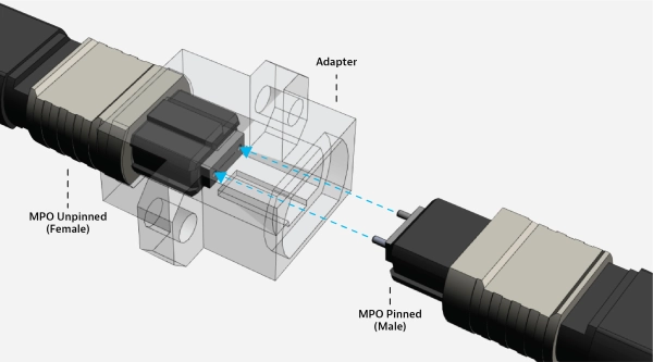
Simplex fiber connections capture two mating cylindrical fiber ends within a cylindrical ceramic split-sleeve, making alignment of the mating fibers quite straight-forward. MPO connectors present the combined challenges of simultaneous multi-fiber alignment and adapter open channels that separate one connector from the other. The multiple fiber positions contribute to tolerance stack-up because the distance and spacing between each fiber creates opportunities for lateral offset and other potential misalignment conditions.
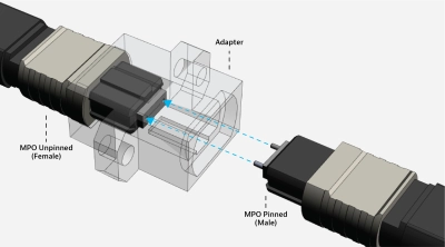
To achieve optimal alignment, MPO fiber connectors utilize two stainless steel alignment pins on one connector and two holes in the same relative position on the mating part. These are also referred to as “male” and “female” configurations, although the nomenclature of “pins” and “no pins” is commonly used. Some manufacturers do provide connector options with removable/replaceable pins, although most connectors in either state cannot be changed in the field, meaning two connectors of the same type cannot be mated to one other.
MPO test equipment that can accept either pinned or unpinned connectors can simplify alignment/configuration issues encountered in MPO testing. During reference verification testing, pinned jumpers can be used to complete the circuit between two unpinned cable connector terminations.
To learn more about MPO alignment, watch our “Understanding MPO Alignment” video:
Click the "Read More" button below to view the transcript
Tyler Vander Ploeg: Hey, everybody. I'm Tyler.
Matt: And Matt.
Tyler Vander Ploeg: And we're from VIAVI solutions, and in this episode we're talking specifically about the challenges of alignment for MPO connectors. Now, with a typical simplex fiber, it's pretty simple.
Matt: Right, that cylinder gets connected to the other cylinder on the other side in a split sleeve, right? So these two things get lined up and aligned. With MPO we've got this array of fibers and we don't have a split sleeve. We have nothing but a wide open channel in the adapter. So, how do MPOs do it? Well, one MPO has to have pins, and the other MPO has to not have pins. So the guide pins on the one MPO go into the guide holes on the other MPO, and that aligns the twelve fibers.
Matt: So, if you've got a pinned connector and you're trying to plug it in to a port that has pins in it, it's not going to work. The thing won't latch in. If you've got an unpinned and you try and connect it to an unpinned, it'll go in but you'll get terrible losses and you'll probably damage the fibers. So, you better have ordered the right gear, or you're not going to be able to plug your link up. And they can't be changed in the field, right? You're stuck with this. You ordered this, this is what you got.
Tyler Vander Ploeg: So this introduces a lot of challenges when it comes to testing.
Matt: Yeah, for sure. One is that my MPO tester needs to be able to plug in to either pinned ports or unpinned ports and test whatever I need it to test. The other is in reference verification, so we're using duplex LCs or Sam Charlies on a simplex or duplex tester, I'm used to verifying that reference condition by taking my light source with its lead and plugging it into my power meter with its lead, and just checking that.
Tyler Vander Ploeg: Simple.
Matt: Just baseline. How's my baseline? Okay, I'm good. With the MPO, if I've got two unpinned MPOs, I can't verify the reference. So now I have to put a third cable in the place, a pinned cable, and I can verify the reference but it's a little more complex and people aren't used to doing it, so it tends to confuse a guy who's used to validating his reference on a simplex tester.
Tyler Vander Ploeg: But there's some new solutions on the market now, right?
Matt: Yeah, good news. I said you can't change them in the field, and you can't with these legacy guys. Our friends at Panduit have a PanMPO™ solution that has pins that can come in and out, it can change itself. Our friends at US Conec have a solution where they have a new connector that you can add pins or remove pins safely in the field. So there's good news that now we've got the ability change it. But mostly, you're going to have to pay attention. The big message is pay attention and look at what you're plugging into each other, because you can damage your connectivity.
Tyler Vander Ploeg: Perfect. Hey, thanks again, Matt. I appreciate it. For more information you can find information online at viavisolutions.com/mpo. Thanks for watching.
MPO Connector Loss
Although fiber misalignment can significantly impact insertion loss associated with the MPO connector interface, other factors including fiber geometry mismatches and the Fresnel reflection induced by air gaps or contamination can also contribute to the overall MPO connector loss.
Since many of the contributing factors to optical loss are related to mechanical limitations or connector tolerances, high-performance connectors may be considered when loss budgets are low and density is high. Test equipment designed with an option to perform optical loss testing on MPO-terminated cables is highly recommended because this reduces the complexity involved in testing MPOs with a single channel OLTS.
To learn more about MPO connector loss, watch our “MPO Testing” video:
Click the "Read More" button below to view the transcript
Tyler Vander Ploeg: Hi everybody. I'm Tyler from VIAVI Solutions. And in this episode I'm talking with Ed Gastle. He's our product line manager for many of our fiber optic test equipment. And he also oversees many of our MPO test instruments. So I wanted to have some time to talk with him a little bit about the different portfolio that we have and what testing is used and when. So Ed, thanks for being on with us.
Ed Gastle: Thanks, Tyler.
Tyler Vander Ploeg: So tell us a little bit when it comes to MPO testing, I know it's been around for a long time, but a lot of folks who are getting into this are asking, okay, what do I need? What kind of test equipment do I need for MPO?
Ed Gastle: MPO testing is not that much different than regular duplex fiber testing in the sense of what tests need to be performed. Obviously the testers are somewhat different. So for the test that you need to perform, you've got your straight on inspection of the fiber end faces and of course it's typically a 12-fiber fair that you have to inspect. You've got your tier one or basic fiber certification, which is your loss, length and polarity. And you also have your tier two or your enhanced testing, which is performing OTDR tests so that you can really see each individual event in that fiber link. So that's really, it's the exact same that you would see for duplex testing. It's just that your tools have to be different because you've got a different fiber connector, being that MPO connector.
Tyler Vander Ploeg: Great, yeah. So we've talked a lot, obviously, about fiber inspection on other episodes and such, but I want to ask a little bit more about when it comes to, you talked about length, loss, and polarity, differentiating when to use a typical MPO to MPO test versus maybe, I know there's applications where MPO is a subset of a greater link. Can you talk a little bit more about when you'd need to use direct MPO testing versus others?
Ed Gastle: Yes. So this is, MPO really has been in networks for quite some time and it's been used as a backbone or a trunk. When you have that backbone or a trunk, then you'll typically have something like a cassette to break down into individual LCs. And those, that still exists and that will get you up, in today's world with multimode, will get you up to 10 gig. If you start to go beyond 10 gig, then you start to need to have different types of connectors out at the end. So that's, this is your cassette. You've got your 24 fibers coming in at the back through MPO, and these need to be inspected. But then your test is done with a classical LTS by testing each of the individual LC drops. So in this case you really don't need to test the trunk assembly. If you do need to troubleshoot it, that's where an OTDR would come into play, and then you can look to find out where a specific fault is. But typically with those trunk assemblies, your issue is your connections that you have, the MPO connections.
Ed Gastle: So then when things start to get different is where you're running at, especially with multimode, 40 and 100 gig, and there are systems like PSM4 for single mode that also run what I would call native MPO right into the equipment, whether it's a switch, a router, a server type of thing. And for that, then you need to start having native MPO interfaces on your test equipment which allow you to test those links and channels. So that's what the, in this case, the MPO LX does, is your basic or tier one certification, your loss, length and polarity. And it's done really much the same way that you would do with an OLTS on LC links. As you do a set reference. You set a limit and then you connect up to your system that you're testing. You perform the test. You get pass/fail. Except you're doing a pass/fail on 12 fibers now instead of two.
Tyler Vander Ploeg: Gotcha. Okay. So very similar behavior. It's still an optical loss test set.
Ed Gastle: Exactly.
Tyler Vander Ploeg: Now, and you said this is more prevalent when you get into that 40 gig, 100 gig with QSFPs and such.
Ed Gastle: With QSFPs, where you've got that direct QSFP or MPO connection into your switch and servers. That's where you need to be, now your link itself, instead of being a duplex LC, your link is an MPO. Typically a 12-fiber MPO. And that's why you need to test that length with native MPO testing. Or you can test the channel as well. Disconnect from the QSFP plugged into the switch, server, router, whatever, and then test the channel.
Tyler Vander Ploeg: Okay. You had briefly mentioned the tier two or enhanced testing as well. Finding out more information. How do you, can you talk a little bit more about some of the new technologies with being able to test an MPO individual lanes with an OTDR.
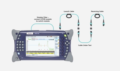
Ed Gastle: So with our 4000 platform, we have a switch module for it. So your OTDR is still a simplex connection, but the simplex connection goes to the switch and the switch gives you that 12-fiber MPO out and because the MPO switch module and the OTDR module are both on the same device, it's really automated. So you say what you want to test. I want to test all 12 fibers. You hit start, and the OTDR tests fiber number one. The switch switches to fiber number two. Test fiber number two, and so on.
Ed Gastle: So you just start it, step back and let it go through all 12 fibers in a, by stepping through with the switch.
Tyler Vander Ploeg: And again, like any OTDR, that gives you the benefit of seeing each individual event through that entire-
Ed Gastle: Correct. And with modern OTDRs, you're, certainly the 4000, is that you're then seeing a schematic view so that you see what the events are and which events have a problem with it instead of having to read a squiggly line on a screen.
Tyler Vander Ploeg: That's perfect. Well, hey, thanks again for joining us, Ed. You also recently wrote a white paper.
Ed Gastle: I did.
Tyler Vander Ploeg: That goes into great depth on this.
Ed Gastle: Yes.
Tyler Vander Ploeg: For more information and to get that white paper that Ed wrote, you can visit us online at viavisolutions.com/mpo. Thanks for watching.
Multi-fiber Push On (MPO) connectors increase your data capacity with a highly efficient use of space. But users have faced challenges such as extra complexities and time required for testing and troubleshooting multi-fiber networks. VIAVI helps overcome these challenges with the industry's most complete portfolio of test solutions for MPO connectivity.
Performing MPO inspection and enterprise testing with tools designed for single fiber applications can be cumbersome and time consuming. With native MPO now running directly to switches, routers and servers in 40/100 Gig applications, advanced testing becomes more essential thus necessitating test equipment with native MPO ports to efficiently test these links and channels.
Inspecting MPO connectors with conventional single fiber inspection tools can difficult because the MPO interface presents unique access and geometry challenges. Dedicated MPO inspection tips can be added to microscopes designed for single fiber connections, but this adaptation process can be time-consuming. An autonomous multi-fiber inspection solution can adequately address the importance of end face inspection in MPO applications, while further automating the inspection practice.
Tier 1 length, loss and polarity testing can be performed with a traditional OLTS and break-out cables from the LC or SC input ports, but this process is improved significantly simply through the introduction of dedicated MPO OLTS equipment. Similarly, OTDR test equipment with dedicated MPO switch ports can conveniently cycle multiple fibers through advanced testing processes
While the use of MPO in fiber networks is not something new, its adoption is becoming increasingly common today. The majority of respondents expect the use of MPO in fiber networks to grow by over 20% in the next 3 years. This rapid growth means it is imperative that both network owner-operators as well as contractors and technicians stay educated on market trends and best practices. The wide variety of new concepts, terms, architectures, and test methods for MPO can be intimidating, but it doesn’t have to be.
To keep things simple, some may think adopting new tools and workflows is unnecessary. After all, if it’s not broken, why fix it, right? While early adopters of new technologies have to count the cost of the time and energy it takes to learn or relearn new methods, the time eventually comes when new methods become best practices. For fiber networks using MPO technology, that time is now. Simply put, well-educated contractors have more opportunity to generate business. Owner operators need to be aware of industry changes, too. There’s no reason they should risk working with contractors who use tools and systems that could negatively impact the overall cost or quality of their networks.
The goal of this page is to help those with a vested interest in fiber technology to better understanding how the growth of multi-fiber connectivity affects how fiber networks are built and efficiently tested, and to arm them with a solid understanding of MPO basics so they’re empowered to choose the right tools for the job. In order to get the lay of the land, we’ll first summarize some key MPO concepts below.
Key MPO Testing Terms and Concepts
Getting a grasp on MPO connectivity can feel intimidating simply because MPO connectors are different than the fiber connectors many technicians are used to (such as LC or SC). Often referred to as “parallel optics”, MPO connectors have an increased number of fibers (8, 12, 24, and more) in a single connector that adds additional factors to consider. This section provides a summary of some of these key terms and concepts.
- Lanes and Speeds
Not only do parallel optics help in achieving needed speeds, they support network migration, too. MPO is no longer just used as a backbone solution, it is now connecting all the way to servers and switches. High speeds are possible by using multiple “lanes” that can be combined together into a single “pipe”. The highest current speed for a “lane” is 50Gbps. To achieve speeds beyond 50Gbps, multiple lanes must be used. One of the easiest ways to achieve this is by using multiple fibers within the same connector, such as an MPO. The following table provides examples.
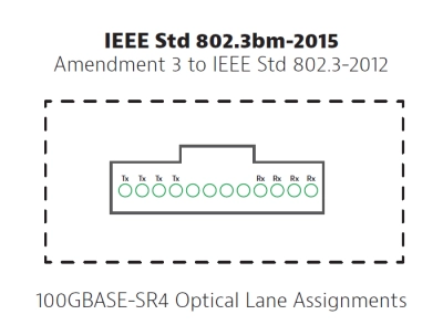
|
Speed per lane |
# of Lanes |
Resulting speed |
MM Technology |
SM Technology |
|
10Gbps |
1 |
10Gbps |
10GBASE-SR |
10GBASE-LX |
|
10Gbps |
4 |
40Gbps |
40GBASE-SR4 |
10GBASE-LR4 |
|
10Gbps |
10 |
100Gbps |
100GBASE-SR10 |
-- |
|
25Gbps |
4 |
100Gbps |
100GBASE-SR4 |
100GBASE-LR4 100 PSM4 |
- Pinned/Un-pinned Configurations
Single-fiber connectors, such as SC or LC are joined by an adapter with a sleeve that lines up the fiber cores of both connectors. For MPO connectors, the alignment is accomplished using one connector with two alignment pins and another with corresponding sockets. While this approach is helpful to ensure that all the fibers are properly aligned, it introduces other challenges when designing networks, mating links, and performing MPO tests.
- MPO Polarity
The term polarity is used in optical networks to ensure that a transmit signal is properly directed to the appropriate receiver. In MPO applications, however, the increased number of fibers makes it more complex as different cable types use different polarity configurations.
- Type A is a straight through connection. The fiber in position 1 is connected to position 1
- Type B is a flipped connection. The fiber in position 1 is connected to position 12. This causes a flip in the fibers which you need to have a 40/100G transmitter talk to a 40/100G receiver.
- Type C is a pairwise flip (fiber 1 to 2, fiber 2 to 1, etc.) used for systems where the end connections are duplex – typically to support 1/10G.
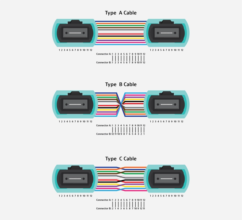
Each method uses a different combination of components, and it is very easy to make mistakes, especially in network upgrade situations where the existing polarity is not known.
- Backbones, Links, and Channels
Backbones
The MPO backbone is the foundational cable for the “link.” Sometimes called a “trunk”, these high-density cables simplify the installation process by consolidating multiple ribbon fibers into a single jacket, rather than running multiple individual cables. Each of the ribbon fibers has MPO connectors on both ends that connect to an adapter panel or a breakout cassette.

Links
A link is the permanent connection between two locations. Typically, it is the cabling between patch panels or distribution frames and can include adapter panels and cassettes. Fiber links can have connections and splices in them. These two locations could be a connection between two racks, or more likely, a rack to a distribution frame of some kind. In some cases, these connection points are high density cassettes that break the MPO down into smaller fiber count connections, such as individual LC or 8-fiber MPO links.

Channels
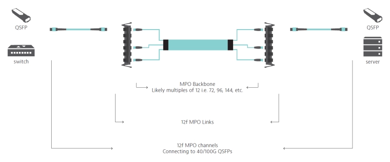
A channel is the connection between equipment. It is made up of the link plus equipment cords (patch cords) at either end of the link. Again, depending on the vernacular you are accustomed to, some people call these equipment cords “patch cords.” In standards parlance, they are called equipment cords, and they are used at each side of a fiber link. In the figure below, there are switches on one side of the link and servers on the other. Depending on your application, there may be switches on either end.

LEARN MORE: White Paper: Testing Parallel Optics
Common MPO Architectures
Now that we’ve covered the basics of key terms and concepts, we’ll consider where you might see MPO connectivity in different forms of architectures.
The versatility of MPO technology makes it a very scalable design solution that can be used in a variety of different architectures. With our understanding of backbone, links and channels in the background, we can consider several possible MPO architectures.
This section highlights seven of the most common scenarios. Though the wide variety of configurations may seem intimidating at first, they represent three basic types of networks. In each scenario, a backbone trunk with MPO connectors is used. As the bandwidth demands increase, so does the amount of MPO connectivity. For continuity purposes, these scenarios all show a connection between servers and switches, however, please keep in mind that MPO can also be used for connectivity between different types of equipment (such as switch-to-switch).
1G/10G MM Channels and 1/10/100G SM Channels
Scenario #1: LC-LC Links (LC-LC Channels)
In the figure below, notice the MPO backbone connected through to cassettes, and the cassettes break down into individual LC links and LC channels when equipment cords are added. When the requirement is to run up to 25G multimode and up to 200G singlemode, using an MPO backbone is much more efficient than running numerous individual LC duplex pairs. In this example the designer chose to run a 72 fiber trunk, and break it into 36 duplex LC links using cassettes. In this scenario, you don’t need to test the backbone fiber, but you will test the link at the front of the LC cassettes.
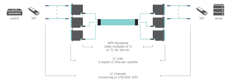
Scenario #2: LC-MPO Links (LC-LC Channels)
Note that the architecture example below is nearly the same as the first example. The difference is that the link on the server side (as shown in the diagram) remains as MPO connectivity and then breaks out to LC after the link with an MPO-LC breakout cable. This is a good design choice when equipment rack-space is at a premium. In this sort of design scenario, also consider the tradeoff of flexibility. At the server end, there is opportunity for more density, and a cleaner solution. However, on the LC cassette side (the left side of the diagram), there’s still a fiber density challenge. In this scenario, one end of your link test will be LC while the other end will be MPO.
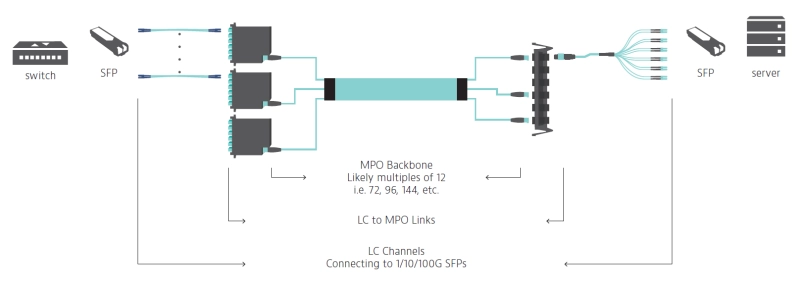
Scenario #3: MPO-MPO Links (LC-LC Channels)
In the figure below, notice that the LC channels are the same as the other configurations. But rather than feeding your equipment with LC connectivity, there is MPO connectivity on both ends of the link. This provides for much more density at the patch panel on each end of the channel. The fiber management is neat and clean at the racks. However, as stated above, this may hinder flexibility. If there is a need to make changes at the switch end, an entire fan-out cable may need to be replaced. In this scenario, both ends of your link test will be MPO.
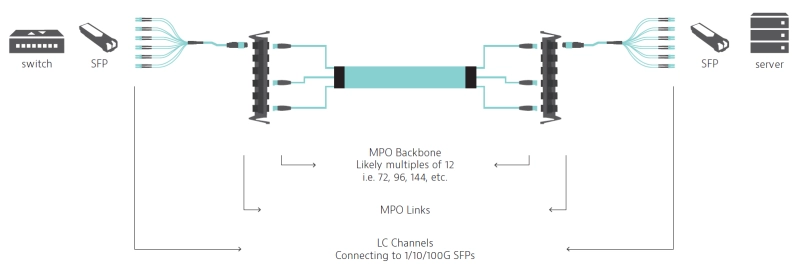
40/100Gbps to 10/25/Gbps
As mentioned in the Lanes and Speeds section, most of the 40/100Gbps architectures only need four lanes (or eight total fibers) of an MPO connector. While the backbone is similar to some 1/10G applications, changes start occurring with the channels as the equipment on the servers and switches begin using QSFP transceivers in places.
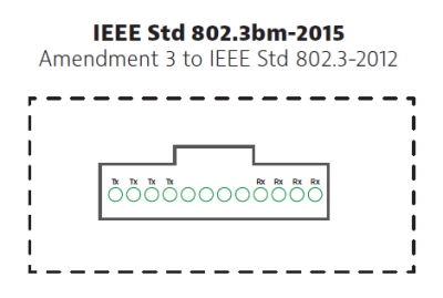
Scenario #4: MPO-MPO Links (MPO-LC channels)
In the figure below, notice that the backbone remains MPO-MPO (like scenario 3). The change here occurs in the channels. The switch (on the left side) now has dedicated QSFP transceivers that an MPO equipment cord can be plugged into. The servers (on the right side) use breakout cables that break the MPO connection out into 4 duplex LC pairs (8 fibers). In this scenario, both ends of your link test will be MPO.

Scenario #5: MPO-LC Links (MPO-LC channels)
In this scenario, note the QSFP at the switch end (on the left side of the diagram). From the backbone the fiber connects into a cassette and breaks down into individual LC connections at the server (as shown on the right side of the diagram). Imagine standing in front of a rack full of four servers. One server on the top, two in the middle, and one on the bottom. In order to achieve 10 or 25G connectivity, place the LC cassette at the top of the rack, run a duplex LC pair down to the bottom server, a duplex LC pair to the third position server, a duplex LC pair down to the second position server, and a duplex LC pair down to the top server. This design is typically used when equipment rack-space is at a premium. In this scenario, one end of your link test will be MPO while the other end will be LC.
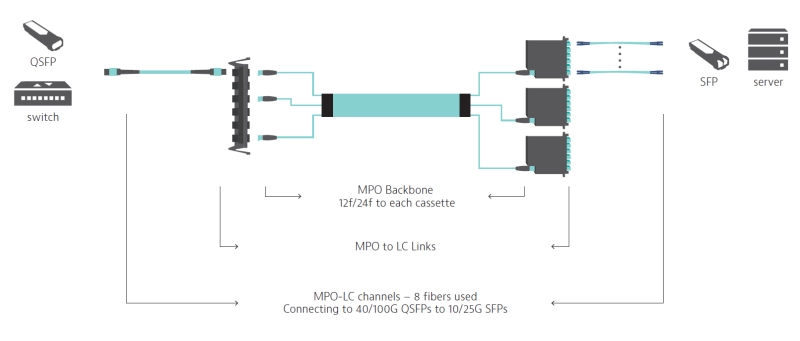
40/100G SR4 (MM) and 100G PSM4 (SM)
Scenario #6: MPO-MPO Links (MPO-MPO channels)
If you are looking to build out a simpler 40 or 100G solution using short-reach four lane technology (SR4), you can replace both ends of the channel with MPO to MPO connectivity. The active equipment uses a Quad Small Form-factor Pluggable transceiver (QSFP) to achieve end to end 40/100G. In this scenario, both ends of your link test will be MPO and you will test only 8 fibers rather than 12.
Scenario #7: MPO-MPO Links (MPO-MPO channels)
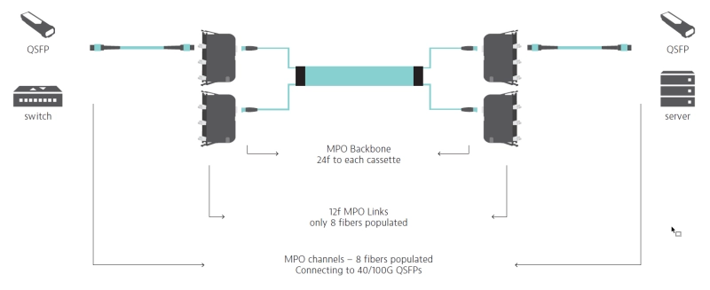
This scenario provides a true high-density 40/100G solution using a combination of different MPO connections. The backbone cable will deliver a series of 24 fiber MPO connectors that each plug into a cassette. Each cassette will break down into three separate, eight fiber connectivity to the QSFP. From a layout perspective this example is no different than scenario example 3, but there are considerations from a testing perspective. In this scenario, both ends of your link test will be MPO and you will test only 8 fibers rather than 12.
Testing MPO
If the various architectures we’ve outlined thus far seem familiar to you, this further underlines the reality that MPO isn’t the exception in fiber networks. It’s commonplace. As networks change, testing needs change as well.
Why MPO Testing Is Important
At the end of the day, network owners and operators should expect their network to be reliable and dependable. For contractors that are hired for install and/or maintenance, they need to make sure their work meets the customer’s requirements. Providing accurate test results that are based on known standards is the guarantee that contractors and network owners can agree upon. After all, contractors need to keep their customers happy, and data center owners need confidence in their networks.
If you are a contractor, a large portion of your business is installing fiber infrastructure, testing and certification of installed fiber confirms that the system you installed supports the applications that will ultimately be carried on the fiber. The certification provides proof that your work was installed according to your customer’s requirements. These requirements are typically based on industry standards. In North America and other parts of the world, the most recognized standard for Optical Fiber Cabling and Components is TIA-568.3. For Europe and other parts of the world, the most recognized standard is IEC 14763-3. While these are different standards, the requirements in each of them are in strong harmonization. Both standards specify two tiers of certification testing for the installed links:
- Tier 1 (or basic): Provide Loss, Length, and Polarity information for each link
- Tier 2 (or extended): Optical Time Domain Reflectometer (OTDR) test information for each link
- Fiber end-face inspection and certification is also a requirement to ensure pristine end-face condition prior to mating
If you’re a network owner or operator, ensuring the integrity of your fiber infrastructure is essential to your business. Whether you manage a large enterprise, run multiple data centers, or a service provider using MPO in your FTTH or FTTA networks, understanding how your fiber network should be tested empowers you to have educated conversations and set clear expectations for your team and the contractors you hire about using the right MPO test tools and procedures to deliver measurable evidence of the network’s capabilities efficiently and within your budget.
MPO Test Scenarios
As highlighted above in the seven common architecture scenarios, there are several ways that MPO connectivity can be used in fiber networks, but don’t let this scare you. While there may be several architectures, there are only three different MPO test scenarios. Following the testing procedure below will result in faster MPO testing, consolidate your reporting, and make your processes more efficient and less expensive.
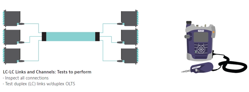
Testing LC-LC configurations that have MPO connections within the links is not different than a typical LC-LC test. As long as the connectors at the end of the link or channel are LC, then the MPO test is the same as other tests performed with LC connections. For a Tier 1 (basic) test, you can use a standard Optical Loss Test Set (OLTS), such as an OLTS-85 that already has native LC ports on the device, so the test cords can be connected directly to the instrument.
As mentioned before, ensuring clean end faces for all fiber connections is essential. For LC-LC links or channels, the LC connectors for both sides of every connection must be inspected with a microscope, however there may be situations where you still need to inspect the MPO-MPO connection behind the cassette.
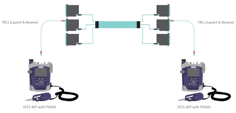
LEARN MORE:Quick Tip Video series - Using the OLTS-85P to perform Tier 1 (basic) tests.
Testing MPO-LC Links or Channels

If you plan to use your existing OLTS to test an MPO-LC configuration, be prepared for much more work. Even though this scenario includes both single-fiber and MPO links, using a dedicated MPO test solution is still the best way to test. Since a typical OLTS does not have a native MPO port on the test device, the process is much more labor intensive. An MPO-LC breakout cable is used on the MPO site to convert the MPO connector into multiple LC connectors. Each of these ends must be inspected, and then MPO tests are performed one duplex pair at a time. Not only does this involve multiple tests, it also means you will have multiple test reports.
Using a purpose-built test instrument like the MPOLx will greatly simplify and streamline this test scenario. Rather than performing multiple MPO tests, the entire link can be certified with a single test. One end (the side with LC connectors) will still utilize a breakout cable, but it will be used to consolidate the multiple fibers so that only one test needs to be performed, with the results all shown in a single test report.
Here is how it is done:
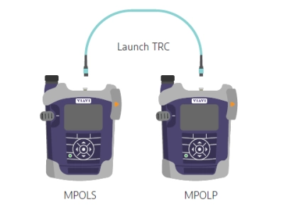
The first thing to do when testing MPO-LC links is to perform a one-cord reference between the MPOLS and your MPOLP. Connect them with a single launch test reference cord, and then do a set reference on your MPOLP, in order to get it to 0dB. Never disconnect from your source, otherwise, you will lose your reference.
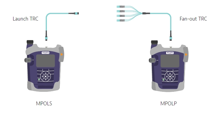
Next, disconnect from the power meter, and on the power meter, attach a fan-out cable. In the example below, note there are four LCs down to a single MPO. Four duplex LCs for eight fiber total.
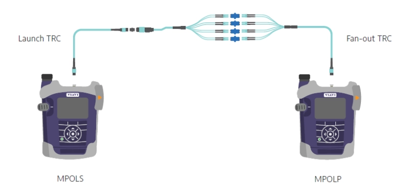
Verify reference: It’s always a good idea to verify your reference. To do this, add a third cable and measure for loss (inspecting each LC first). The loss should be .35dB or better, because you’ve added in two connections. Now, these two connections should be quite low-loss connections, because you should be using reference-grade connectors as much as you can, particularly on the LC side.
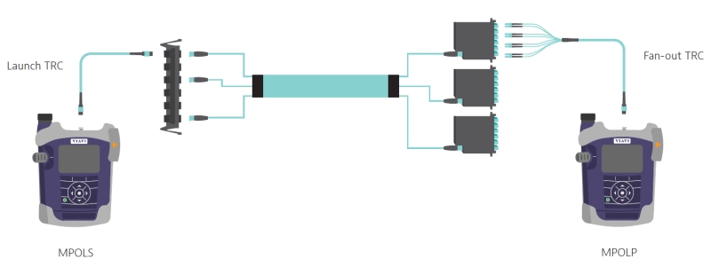
Once you verify that, then you remove your third TRC, and connect to your system under test. Now you measure loss of the link.
Testing MPO-MPO Links or Channels
Like the previous scenario, using a test set that is purpose built for MPO certification is much more effective than using a legacy OLTS. This scenario is most common in the 40/100G scenarios, and it is also the simplestif you are using purpose built MPO test tools.
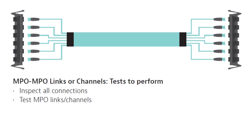
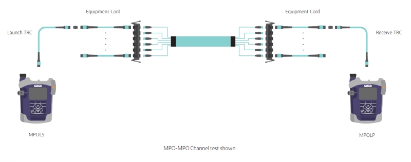
LEARN MORE: Quick Tip Video series - Using the MPOLx to perform Tier 1 (basic) tests for MPO-MPO connections
The following table summarizes how each of these MPO test scenarios are applied to the architecture scenarios previously mentioned. As shown, 10 of the 14 scenarios involve testing an MPO connection directly. Using a purpose-built MPO test device such as the MPOLx will greatly simplify and streamline this testing.
| Test Scenario |
Architecture Scenario |
|
LC-LC |
#1 (Link Test & Channel Test) |
|
MPO-LC |
#2 (Link Test) |
|
MPO-MPO |
#3 (Link Test) |
In the last several sections, we’ve gotten technical in order to cover the basics of MPO networks, and to show that while there are several MPO testing scenarios, they basically boil down to three different kinds of networks.
Challenges with Legacy Test Procedures
The Challenges of MPO Using Single/Duplex Fiber Testing Tools
When a technician uses a traditional single-fiber test instrument in an MPO application, there are some built-in challenges and complexities. When you test an MPO network with a legacy tool, it’s like using a pickaxe and shovel for a much bigger job. You can certainly get the job done, but you need to ensure the job is done quickly and efficiently. A legacy tool may not be your best solution. For one, fanout cables get messy during MPO test procedures and deciphering which break-out strand corresponds to which fiber can be tricky. In addition, maintaining the performance quality of these reference cables over time requires proper care with end face inspection and cleaning. If one dust cap gets lost, the exposed end can get damaged, making the entire cable useless. It’s like hitting that water pipe and gaining a new problem you hadn’t bargained for.
In an environment where a legacy tool process is used, a typical OLTS has either LC or SC input ports. In this scenario, it’s not possible to plug an MPO connector into the test device. Instead an additional break-out/fan-out assembly is added between the MPO connector and the Test Reference Cables (TRCs) that connect to the test instrument port. These types of hybrid cables are necessary when MPO testing with legacy tools, and the process becomes unnecessarily complicated (as seen in the figure below).

LEARN MORE: Use Case: Testing MPO Networks
Benefits of New MPO Test Solutions
Technicians with history in the world of fiber are accustomed to working with single fiber connectors (whether they are SC or LC.) Making changes to their testing procedures may feel daunting and adopting new tools and changing processes always comes with a learning curve. But these purpose-built MPO tools enable simpler testing processes. In the figure below, notice that each device features native MPO ports. This means fan-out cables are unnecessary. An MPO connectorized test reference cord connects directly to the device under test (DUT). Also, note that devices such as the VIAVI MPOLx features a built-in microscope that allows the user to inspect the TRC cables and eliminate the need for additional tools with video display screens.
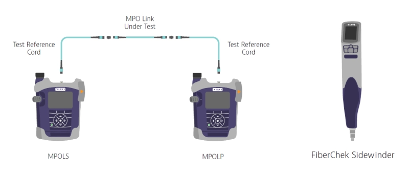
LEARN MORE: Use Case: Testing MPO Networks
End-Face Inspection
Using purpose-built tools for fiber inspection is also much faster and easier. In recent years, VIAVI Solutions has published many resources related to fiber inspection, and fiber end-face cleanliness as part of our “Inspect Before You Connect” message. Although the standards bodies have established acceptance criteria for quality and cleanliness control of fiber end faces, it’s still an ongoing problem for technicians in the field. Debris on the end of a fiber connector can range from 2 - 15μm and is not visible to the naked eye. It’s imperative to inspect both sides of the fiber connection and ensure test ports and reference cords are clean as well to make sure there’s no debris cross contamination.
Winning with MPO Testing
While there are certainly new complexities to consider, there’s no need to fear how MPO is changing fiber networks. Our hope is that we’ve simplified some MPO concepts that some may find intimidating. Throughout this article, we have referenced various resources that will equip you with the knowledge you need to install and service MPO networks effectively.
If you’re an owner/operator of a network, you’re responsible for ensuring savings on MPO testing processes. You’re counting on reliable test results, and you can’t afford to hire contractors that don’t use purpose-built MPO testing tools. Using legacy tools in an MPO environment requires too many workarounds you simply can’t afford. You need to have confidence in the accuracy of your MPO test results, and you should feel empowered to expect the best from your contractors.
If you’re a contractor, having specialized fiber knowledge is no longer considered to be a mythical power like it was ten or fifteen years ago. It’s simply required knowledge. You need to be conversant with the changing needs of customers. You don’t want to get caught unprepared to test a robust MPO application with legacy tools. Now you have all the necessary information to succeed, remain competitive, and strengthen your business in the ever-changing world of fiber technology.
Start testing MPO connectors with help from VIAVI today!
Are you ready to take the next step with one of our MPO test products or solutions?
Complete one of the following forms to get going:
